以前、joystickで亀を動かした。今回は亀の代わりにモーターをコントロールする。これは次の投稿を組み合わせたものになる。
●[ROS2]ROS2にjoystickを接続してみた
●DCモータードライバーDRV8871を使ってみる
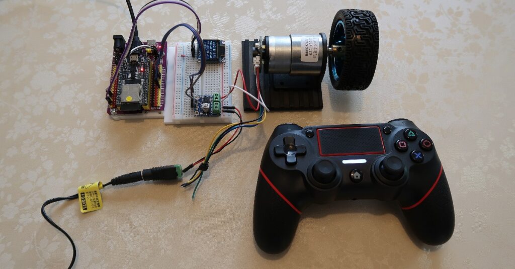
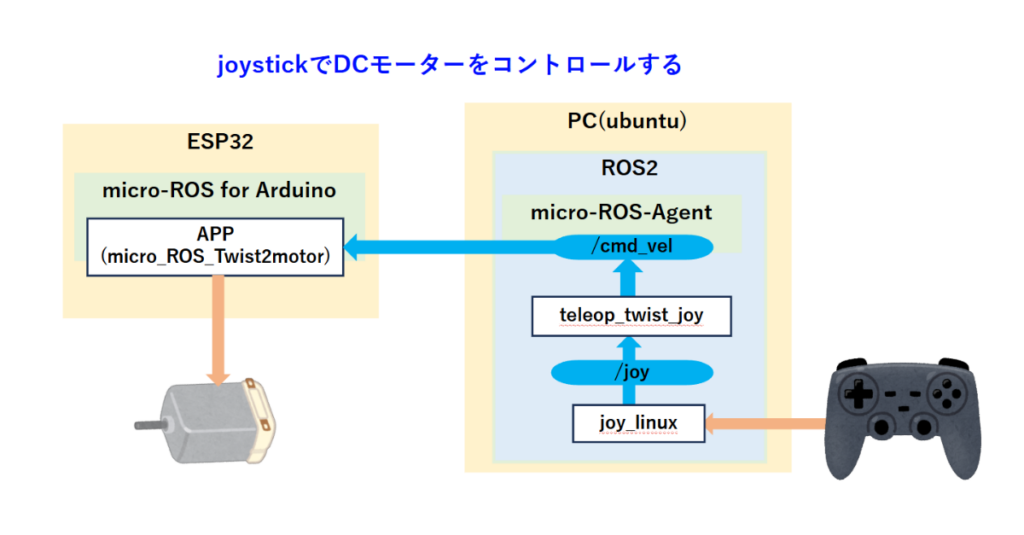
上図のパッケージjoy_linuxとteleop_twist_joyは、ネットからインストールできる。従ってESP32のアプリケーションだけを作ればよい。
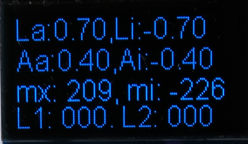
上の画像は、OLEDの表示画面である。上の行から順に
トピック/cmd_velのlinear.xの最高値と最低値
トピック/cmd_velのangular.zの最高値と最低値
トピック/cmd_velからモーター制御用のPWM値に変換した最高値と最低値
モータードライバー端子に出力中の現在値
を示している。linear.xとangular.zは、ステックを回せる範囲で最も大きく回しているので、これが実際に出力される最大値と考えられる。
/cmd_velの型は、geometry_msgs/msg/Twistでこのうち直進成分のlinear.xと回転成分のangular.zだけを使う。これからモーターを回すPWM値を作る。PWM値は分解能8bitに設定するので0~255になる。
int motor_L = msg->linear.x * 255 + msg->angular.z * 255; 今回使用するモータードライバーDRV8871は、正回転時はドライバーの入力ピンIN1を0にしてIN2に255までの正の値を入力する。逆回転の場合は、IN1とIN2の値を逆にする。上記motor_Lの値が正ならば正回転、負ならば逆回転とする。
また、PWMの値がある値より小さい場合は、モーターは回転しない。モーターが回転するぎりぎりの値を下限値とし、それより小さなPWM値は0に見なしている。上限値は255としmotor_Lの絶対値がこれを超える場合は、255に設定しなおしている。
使い方
[端末1] --- PC上でmicro-ROS-Agentを起動する。
sudo docker run -it --rm -v /dev:/dev --privileged --net=host microros/micro-ros-agent:jazzy udp4 --port 8888

[端末2] --- joystickの操作から/joyトピックをパブリッシュする。
ros2 run joy_linux joy_linux_node

[端末3] --- トピックjoy_velをturtlesimのtopicに変更してcmd_velをパブリッシュする。
ros2 launch teleop_twist_joy teleop-launch.py joy_vel:=/cmd_vel

------------------------------------------------------------------------- 以下、必要に応じて

# pubコマンドで/cmd_velをパブリッシュする。一定のスピードで回す場合に使う。
ros2 topic pub --rate 1 /cmd_vel geometry_msgs/msg/Twist "{linear: {x: 0.5, y: 0.0, z: 0.0}, angular: {x: 0.0, y: 0.0, z: 0.3}}"

# キーボードからトピック/cmd_velをパブリッシュする。ジョイステックで想定する最大値を超えるので特別な理由がなければ使わない。
ros2 run turtlesim turtle_teleop_key --ros-args --remap /turtle1/cmd_vel:=/cmd_vel
作成したESP32のアプリ
micro_ROS_Twist2Motor_ESP32
#include <dummy.h>
/* micro_ROS_Twist2Motor_ESP32 2025.01.18
【概要】twist型のトピックをsubscribeして、DC motorを回す。
受信したメッセージとモーター出力をOLEDに表示する。
linear.x, msg->angular.z
subscribe: /cmd_vel (Twist)
*/
#include <Arduino.h>
#include <micro_ros_arduino.h>
#include <stdio.h>
#include <rcl/rcl.h>
#include <rcl/error_handling.h>
#include <rclc/rclc.h>
#include <rclc/executor.h>
#include <geometry_msgs/msg/twist.h>
#include <Wire.h> // SSD1306 — OLED用
#include “SSD1306.h” // SSD1306用ライブラリを読み込み
SSD1306 display(0x3c, 21, 22); //SSD1306インスタンスの作成(I2Cアドレス,SDA,SCL)
const int motor1Pin1 = 12;
const int motor1Pin2 = 13;
const int MAX_SPEED = 254; // 最大スピード
const int MIN_SPEED = 70; // 最小スピード
//—– グローバル変数に行ごとの内容を保持
String line1 = “msg_cnt: 0”; // 1行目
String line2 = “”; // 2行目
String line3 = “”; // 3行目
String line4 = “”; // 4行目
rcl_node_t node;
rclc_support_t support;
rcl_allocator_t allocator;
rcl_init_options_t init_options; //[追加]
rmw_init_options_t* rmw_options; //[追加]
rcl_subscription_t subscriber_tw;
geometry_msgs__msg__Twist msg;
#define STR_SIZE (100) //最大の受信文字数
rclc_executor_t executor_sub;
#define DOMAIN_ID 1 //[追加]
#define LED_PIN 2
#define RCCHECK(fn) \
{ \
rcl_ret_t temp_rc = fn; \
if ((temp_rc != RCL_RET_OK)) \
{ \
error_loop(); \
} \
}
#define RCSOFTCHECK(fn) \
{ \
rcl_ret_t temp_rc = fn; \
if ((temp_rc != RCL_RET_OK)) \
{ \
} \
}
int sub_cnt = 0; // subscription回数
int motor_L_max = 0;
int motor_L_min = 0;
const float FLT_MAX = 0.0;
float linear_x_max = FLT_MAX;
float linear_x_min = FLT_MAX;
float angular_z_max = FLT_MAX;
float angular_z_min = FLT_MAX;
/**
* @brief loop to indicate error with blinking LED
*
*/
void error_loop()
{
while (1)
{
digitalWrite(LED_PIN, !digitalRead(LED_PIN));
//[追加] OLEDにエラーを表示する。
String err_msg = “”;
if (LED_PIN == 0) {
err_msg = ” Error”;
} else {
err_msg = ” “;
}
display.drawString(0, 17, err_msg);
display.display(); // 画面を表示する
}
delay(200);
}
/**
* @brief subscription callback executed at receiving a message
*
* @param msgin
*/
//———————————————————————— cmd_velのコールバック関数
void subscription_callback_twist(const void *msgin) {
const geometry_msgs__msg__Twist *msg = (const geometry_msgs__msg__Twist *)msgin;
//—– 最大値, 最小値取得
if (msg->linear.x > linear_x_max) linear_x_max = msg->linear.x;
if (msg->linear.x < linear_x_min) linear_x_min = msg->linear.x;
if (msg->angular.z > angular_z_max) angular_z_max = msg->angular.z;
if (msg->angular.z < angular_z_min) angular_z_min = msg->angular.z;
char buf_l1[32];
sprintf(buf_l1, “La:%.2f,Li:%.2f”, linear_x_max, linear_x_min);
line1 = buf_l1;
char buf_l2[32];
sprintf(buf_l2, “Aa:%.2f,Ai:%.2f”, angular_z_max, angular_z_min);
line2 = buf_l2;
// cmd_velをPWM出力に変換する。
int motor_L = msg->linear.x * 255 + msg->angular.z * 255;
// 最大値, 最小値取得
if (motor_L > motor_L_max)
motor_L_max = motor_L;
if (motor_L < motor_L_min)
motor_L_min = motor_L;
char buf_l3[32];
sprintf(buf_l3, “mx: %03d, mi: %03d”, motor_L_max, motor_L_min);
line3 = buf_l3;
// PWM出力の上限値チェック
if (abs(motor_L) > MAX_SPEED)
{
if (motor_L > 0)
motor_L = MAX_SPEED;
else
motor_L = -MAX_SPEED;
}
// PWM出力の下限値チェック
else if (abs(motor_L) < MIN_SPEED)
motor_L = 0;
// モーター出力をドライバーへの出力に変換する
int motor_L_IN1, motor_L_IN2;
if (motor_L > 0)
{
motor_L_IN1 = motor_L;
motor_L_IN2 = 0;
}
else
{
motor_L_IN1 = 0;
motor_L_IN2 = abs(motor_L);
}
analogWrite(motor1Pin1, motor_L_IN1);
analogWrite(motor1Pin2, motor_L_IN2);
//—– 4行目の内容を更新 モーター出力値
char buf_l4[32];
sprintf(buf_l4, “L1: %03d, L2: %03d”, motor_L_IN1, motor_L_IN2);
line4 = buf_l4;
//—– OLED表示
display.clear(); // 画面をクリア
display.drawString(0, 0, line1); // 1行目の表示
display.drawString(0, 17, line2); // 2行目の表示
display.drawString(0, 34, line3); // 3行目の表示
display.drawString(0, 49, line4); // 4行目の表示
display.display(); // 画面を更新
}
void setup()
{
//[追加]—– 初期画面表示
display.init(); //ディスプレイを初期化
display.setFont(ArialMT_Plain_16); //フォントを設定
display.drawString(0, 0, “*Program name*”); //(0,0)の位置に表示
display.drawString(0, 17, “micro_ROS_Twis”);
display.drawString(0, 34, “t2motor_ESP32”);
display.display(); //指定された情報を描画
// DC motor
pinMode(motor1Pin1 , OUTPUT);
pinMode(motor1Pin2 , OUTPUT);
analogWrite(motor1Pin1, 0);
analogWrite(motor1Pin2, 0);
set_microros_wifi_transports(“aterm-2b4139-a”, “3e00cfa4ba409”, “192.168.0.63”, 8888);
pinMode(LED_PIN, OUTPUT);
digitalWrite(LED_PIN, HIGH);
delay(3000);
allocator = rcl_get_default_allocator();
// Init options to use domain id —- DOMEIN IDを設定する
init_options = rcl_get_zero_initialized_init_options();
RCCHECK(rcl_init_options_init(&init_options, allocator));
rmw_options = rcl_init_options_get_rmw_init_options(&init_options);
rcl_init_options_set_domain_id(&init_options, (size_t)DOMAIN_ID);
RCCHECK(rclc_support_init_with_options(&support, 0, NULL, &init_options, &allocator));
// create node
RCCHECK(rclc_node_init_default(&node, “micro_ros_xiao_node”, “”, &support));
// create subscriber ————————————————————— cmd_vel 2025.01.11
RCCHECK(rclc_subscription_init_default(
&subscriber_tw,
&node,
ROSIDL_GET_MSG_TYPE_SUPPORT(geometry_msgs, msg, Twist),
“cmd_vel”));
// create executor —- subscriber
RCCHECK(rclc_executor_init(&executor_sub, &support.context, 1, &allocator));
RCCHECK(rclc_executor_add_subscription(&executor_sub, &subscriber_tw, &msg, &subscription_callback_twist, ON_NEW_DATA));
}
void loop()
{
delay(10);
RCCHECK(rclc_executor_spin_some(&executor_sub, RCL_MS_TO_NS(100)));
}