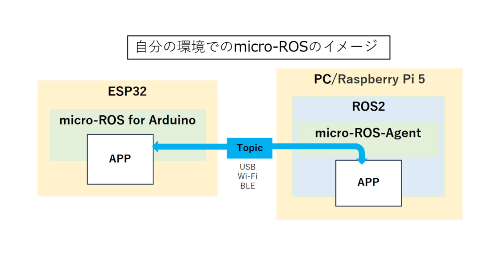
micro-ROSを使うとマイコン上にROS2のノードを作れるということなのでやってみた。
ESP32のAPPでトピックを直接扱えるのはありがたい。
micro-ROS-AgentをPCやRasb\pberry Piなどのどこかで起動していれば、通信を意識しなくてよくなる。
しかもmicro-ROS-AgentはDocker一発でインストールと起動ができるので楽に使える。
Arduino IDEへmicro_ros_arduinoライブラリをインストールするやり方はTakumi Asadaの記事を参考にさせて頂いた。
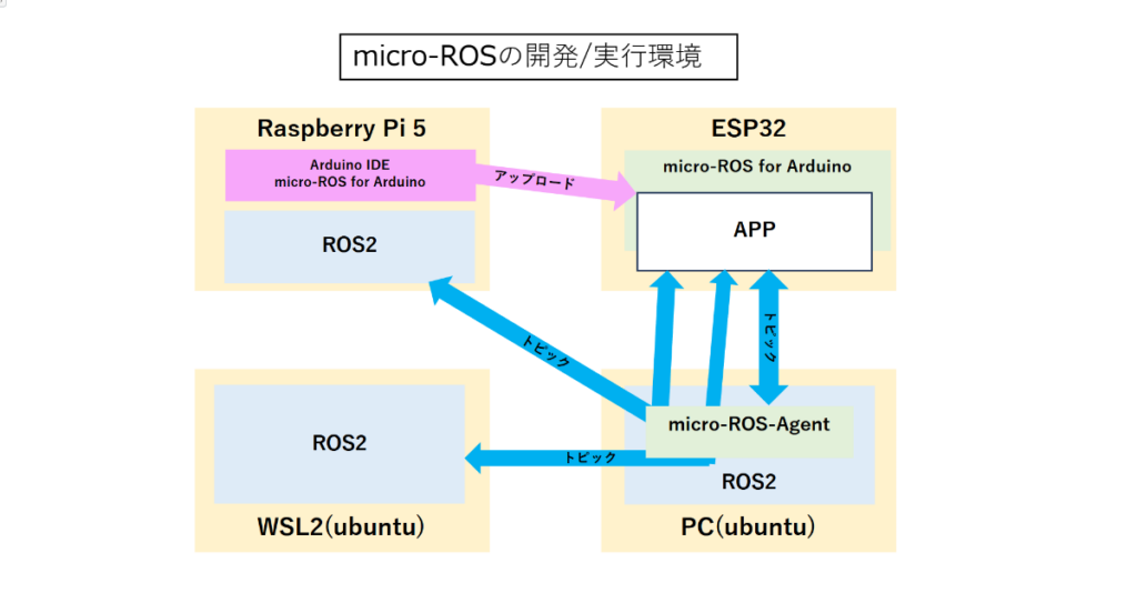
環境
現在の環境は下図の通り。
ESP32のプログラムは、ラズパイ5上のArduino IDE 1.8.19で作成し、アップロードする。
現在、ESP32との接続はすべてWi-Fiとし、micro-ROS-AgentはPCのubuntuに固定。
PC, ラズパイ5, WSL2のDOMAIN_IDを1に設定していて、ESP32のAPPとはいずれからも通信可能。
micro-ROS-Agentは、PCでもラズパイ5でも「使い方」のDockerコマンドでインストールが可能なのでこれで良しとする。但しWSL2では使えなかった。
動作確認
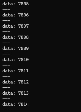
例題の「micro_ros_publisher_wifi.ino」を少し修正して動作確認用プログラムとする。
プログラム内でカウントアップした整数がパブリッシュされる(画像参照)。
使用中の環境は、DOMAIN_IDを1に設定しているので同様にDOMAIN_IDをに設定した。
micro_ROS_Agent を起動したPCのIPアドレスを環境に合わせて修正すること。
micro_ros_publisher_wifi_DOMAIN_ID
/* micro_ros_publisher_wifi_DOMAIN_ID   2025.1.12

例題プログラム micro_ros_publisher_wifi にDOMAIN_ID 1 を追加した。

*/
#include <micro_ros_arduino.h>

#include <stdio.h>
#include <rcl/rcl.h>
#include <rcl/error_handling.h>
#include <rclc/rclc.h>
#include <rclc/executor.h>

#include <std_msgs/msg/int32.h>

#if !defined(ESP32) && !defined(TARGET_PORTENTA_H7_M7) && !defined(ARDUINO_NANO_RP2040_CONNECT) && !defined(ARDUINO_WIO_TERMINAL)
#error This example is only avaible for Arduino Portenta, Arduino Nano RP2040 Connect, ESP32 Dev module and Wio Terminal
#endif

rcl_publisher_t publisher;
std_msgs__msg__Int32 msg;
rclc_support_t support;
rcl_allocator_t allocator;
rcl_node_t node;

rcl_init_options_t init_options; //[追加]
rmw_init_options_t* rmw_options; //[追加]

#define DOMAIN_ID 1 //[追加]
#define LED_PIN 2     // 13 -> 2

#define RCCHECK(fn) { rcl_ret_t temp_rc = fn; if((temp_rc != RCL_RET_OK)){error_loop();}}
#define RCSOFTCHECK(fn) { rcl_ret_t temp_rc = fn; if((temp_rc != RCL_RET_OK)){}}


void error_loop(){
  while(1){
    digitalWrite(LED_PIN, !digitalRead(LED_PIN));
    delay(100);
  }
}

void timer_callback(rcl_timer_t * timer, int64_t last_call_time)
{
  RCLC_UNUSED(last_call_time);
  if (timer != NULL) {
    RCSOFTCHECK(rcl_publish(&publisher, &msg, NULL));
    msg.data++;
  }
}

void setup() {
  set_microros_wifi_transports("aterm-2b4139-a", "3e00cfa4ba409", "192.168.0.63", 8888);

  pinMode(LED_PIN, OUTPUT);
  digitalWrite(LED_PIN, HIGH);

  delay(2000);

  allocator = rcl_get_default_allocator();

  // create init_options ---------------------- オリジナル
  //RCCHECK(rclc_support_init(&support, 0, NULL, &allocator));  --------------------- オリジナル

  // Init options to use domain id ---- DOMEIN IDを設定する
  init_options = rcl_get_zero_initialized_init_options();
  RCCHECK(rcl_init_options_init(&init_options, allocator));
  rmw_options = rcl_init_options_get_rmw_init_options(&init_options);
  rcl_init_options_set_domain_id(&init_options, (size_t)DOMAIN_ID);
  RCCHECK(rclc_support_init_with_options(&support, 0, NULL, &init_options, &allocator));

  // create node
  RCCHECK(rclc_node_init_default(&node, "micro_ros_arduino_wifi_node", "", &support));

  // create publisher
  RCCHECK(rclc_publisher_init_best_effort(
    &publisher,
    &node,
    ROSIDL_GET_MSG_TYPE_SUPPORT(std_msgs, msg, Int32),
    "topic_name"));

  msg.data = 0;
}

void loop() {
    RCSOFTCHECK(rcl_publish(&publisher, &msg, NULL));
    msg.data++;
}
使い方
[端末1] --- PC上でmicro-ROS-Agentを起動する。
sudo docker run -it --rm -v /dev:/dev --privileged --net=host microros/micro-ros-agent:jazzy udp4 --port 8888

[端末2] --- ESP32からのトピックを表示する。 --- PC, Raspi5, WSL2
ros2 topic echo /topic_name
エコープログラム
String型のデータをサブスクライブしてそのままパブリッシュするプログラム。ESP32でも状態が分かるようにサブスクライブしたデータをOLED(SSD1306)に表示する。
micro_ROS_pub_sub_OLED
#include <dummy.h>

/* micro_ROS_pub_sub_OLED.ino   2024.7.31
【概要】受信したメッセージをエコーバックする。
      String型のトピックをsubscribeして、メッセージに受信回数を付加してpublishする。
      受信したメッセージをOLEDに表示する。

  subscribe: /recv (String)
  publish:   /echo (String)

*/

#include <Arduino.h>
#include <micro_ros_arduino.h>

#include <stdio.h>
#include <rcl/rcl.h>
#include <rcl/error_handling.h>
#include <rclc/rclc.h>
#include <rclc/executor.h>

#include <std_msgs/msg/string.h>

#include <Wire.h>               // SSD1306 --- OLED用
#include "SSD1306.h"            // SSD1306用ライブラリを読み込み
SSD1306  display(0x3c, 21, 22); //SSD1306インスタンスの作成(I2Cアドレス,SDA,SCL)

rcl_node_t node;
rclc_support_t support;
rcl_allocator_t allocator;

rcl_init_options_t init_options; //[追加]
rmw_init_options_t* rmw_options; //[追加]


// publisher
rcl_publisher_t publisher;
std_msgs__msg__String send_string_msg;
rclc_executor_t executor_pub;
rcl_timer_t timer;

// subscriber
rcl_subscription_t subscriber;
std_msgs__msg__String recv_string_msg;
#define STR_SIZE (100) //最大の受信文字数
rclc_executor_t executor_sub;

#define DOMAIN_ID 1 //[追加]
#define LED_PIN 2

#define RCCHECK(fn)              \
  {                              \
    rcl_ret_t temp_rc = fn;      \
    if ((temp_rc != RCL_RET_OK)) \
    {                            \
      error_loop();              \
    }                            \
  }
#define RCSOFTCHECK(fn)          \
  {                              \
    rcl_ret_t temp_rc = fn;      \
    if ((temp_rc != RCL_RET_OK)) \
    {                            \
    }                            \
  }

int sub_cnt = 0; // subscription回数

/**
 * @brief loop to indicate error with blinking LED
 *
 */
void error_loop()
{
  while (1)
  {
    digitalWrite(LED_PIN, !digitalRead(LED_PIN));
    //[追加] OLEDにエラーを表示する。
    String err_msg = "";
    if (LED_PIN == 0) {
      err_msg = "    Error";

    } else {
      err_msg = "          ";
    }
  display.drawString(0, 17, err_msg);
  display.display();     // 画面を表示する
  }
  delay(200);
}

int cnt = 0;
void timer_callback(rcl_timer_t *timer, int64_t last_call_time)
{
  RCLC_UNUSED(last_call_time);
  if (timer != NULL)
  {
    //RCSOFTCHECK(rcl_publish(&publisher, &send_string_msg, NULL));
    //msg_heartbeat.data++;
    cnt++;
  }
}

/**
 * @brief subscription callback executed at receiving a message
 *
 * @param msgin
 */
void subscription_callback(const void *msgin)
{
  const std_msgs__msg__String *recv_string_msg = (const std_msgs__msg__String *)msgin;

  // (condition) ? (true exec):(false exec)
  //digitalWrite(LED_PIN, (recv_string_msg->data == 0) ? LOW : HIGH);

  sub_cnt++; // subscription回数カウントアップ
  // 送信メッセージ
  String s = String(recv_string_msg->data.data) + String(sub_cnt);

  //----- OLED表示
  display.init();       // 表示クリア
  // 1行目のテキストの表示 --- subscription回数
  display.drawString(0, 0, "msg_cnt: "+String(sub_cnt));
  // 2行目のテキストの表示 --- メッセージ + subscription回数
  String line2 = String(recv_string_msg->data.data);
  display.drawString(0, 17, line2);
  display.display();            // 画面を表示する。

  // 送信メッセージをpublish形式に変換する。
   char strBuf[120];
  s.toCharArray(strBuf, 120);
  send_string_msg.data.size = s.length();
  send_string_msg.data.data = strBuf;

  RCSOFTCHECK(rcl_publish(&publisher, &send_string_msg, NULL));
}

void setup()
{
  //[追加]----- 初期画面表示
  display.init();    //ディスプレイを初期化
  display.setFont(ArialMT_Plain_16);    //フォントを設定
  display.drawString(0, 0, "*Program name*");    //(0,0)の位置に表示
  display.drawString(0, 17, "micro_ROS_pub_sub_OLED.ino");
  display.drawString(0, 34, "sub_OLED.ino");
  display.display();   //指定された情報を描画

  //set_microros_transports();
  set_microros_wifi_transports("aterm-2b4139-a", "3e00cfa4ba409", "192.168.0.63", 8888);

  pinMode(LED_PIN, OUTPUT);
  digitalWrite(LED_PIN, HIGH);

  delay(3000);

  allocator = rcl_get_default_allocator();

  // create init_options ---------------------- オリジナル
  //RCCHECK(rclc_support_init(&support, 0, NULL, &allocator));  --------------------- オリジナル

  // Init options to use domain id ---- DOMEIN IDを設定する
  init_options = rcl_get_zero_initialized_init_options();
  RCCHECK(rcl_init_options_init(&init_options, allocator));
  rmw_options = rcl_init_options_get_rmw_init_options(&init_options);
  rcl_init_options_set_domain_id(&init_options, (size_t)DOMAIN_ID);
  RCCHECK(rclc_support_init_with_options(&support, 0, NULL, &init_options, &allocator));


  // create node
  RCCHECK(rclc_node_init_default(&node, "micro_ros_xiao_node", "", &support));

  // create subscriber
  // const char topic_name_led[] = "recv";
  RCCHECK(rclc_subscription_init_default(
      &subscriber,
      &node,
      ROSIDL_GET_MSG_TYPE_SUPPORT(std_msgs, msg, String),
      "recv"));

  // create publisher
  // const char topic_name_heatbeat[] = "echo";
  RCCHECK(rclc_publisher_init_default(
      &publisher,
      &node,
      ROSIDL_GET_MSG_TYPE_SUPPORT(std_msgs, msg, String),
      "echo"));

  // create timer, called every 1000 ms to publish heartbeat
  const unsigned int timer_timeout = 500;
  RCCHECK(rclc_timer_init_default(
      &timer,
      &support,
      RCL_MS_TO_NS(timer_timeout),
      timer_callback));

  // create executor
  RCCHECK(rclc_executor_init(&executor_pub, &support.context, 1, &allocator));
  RCCHECK(rclc_executor_add_timer(&executor_pub, &timer));

  RCCHECK(rclc_executor_init(&executor_sub, &support.context, 1, &allocator));
  RCCHECK(rclc_executor_add_subscription(&executor_sub, &subscriber, &recv_string_msg, &subscription_callback, ON_NEW_DATA));

  // char型変数を入れる配列を確保する
  recv_string_msg.data.data = (char * )malloc(STR_SIZE * sizeof(char));
  recv_string_msg.data.size = 0;
  recv_string_msg.data.capacity = STR_SIZE;

}

void loop()
{
  delay(10);
  RCCHECK(rclc_executor_spin_some(&executor_pub, RCL_MS_TO_NS(100)));
  RCCHECK(rclc_executor_spin_some(&executor_sub, RCL_MS_TO_NS(100)));
}
使い方
[端末1] --- PC上でmicro-ROS-Agentを起動する。
sudo docker run -it --rm -v /dev:/dev --privileged --net=host microros/micro-ros-agent:jazzy udp4 --port 8888

[端末2] --- ESP32のノードにトピックを送る。 --- PC, Raspi5, WSL2
ros2 topic pub --once /recv std_msgs/msg/String "{data: 'hello world'}"

[端末3] --- ESP32からのトピックを表示する。 --- PC, Raspi5, WSL2
ros2 topic echo /echo
課題
●ESP32C3用のmicro-ROS for Arduinoがまだない
esp32S3 または esp32C3 のアップデート計画はありますか? #1820
●WSL2をインストールしたPCでESP32C3はCOMボートを認識するが、ESP32は認識しない
micro-ROSの開発環境はRaspi5になる。
●Raspi5とWSL2のROS2でトピックが通らない。——–[解決]
Raspi5をファイアウォールの「リモートIPアドレス」に追加が抜けていた。参照(WSL2にミラーモードを設定する)