


概要
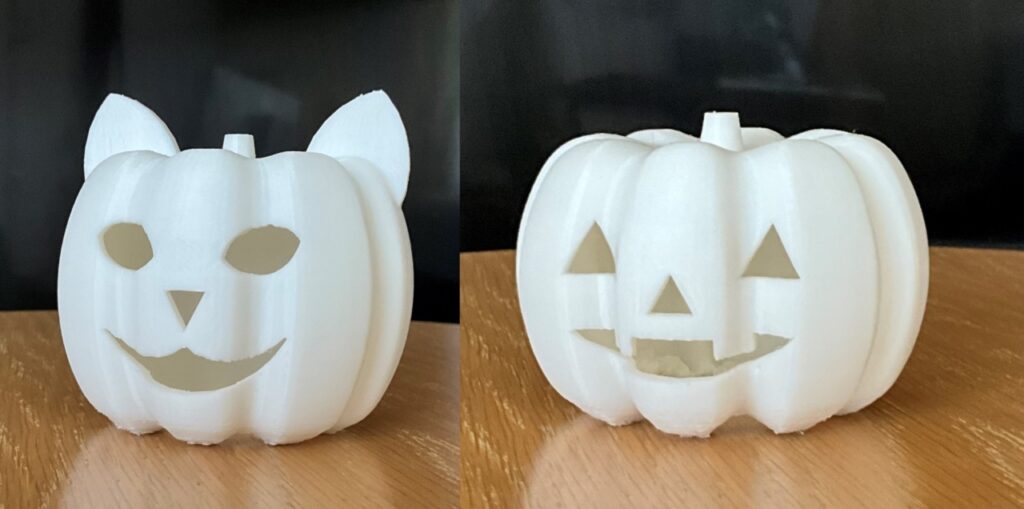
ハロウィーン用のカボチャを3Dプリンターで作り、カラーLEDで光らせます。
最初にカボチャを作り、次にESP32マイコンでLEDを光らせる順に概要を説明します。
3DCGソフトでかぼちゃの形を作る

3Dコンピュータグラフィックスの制作によく使われるソフトBlenderでかぼちゃの形を作ります。
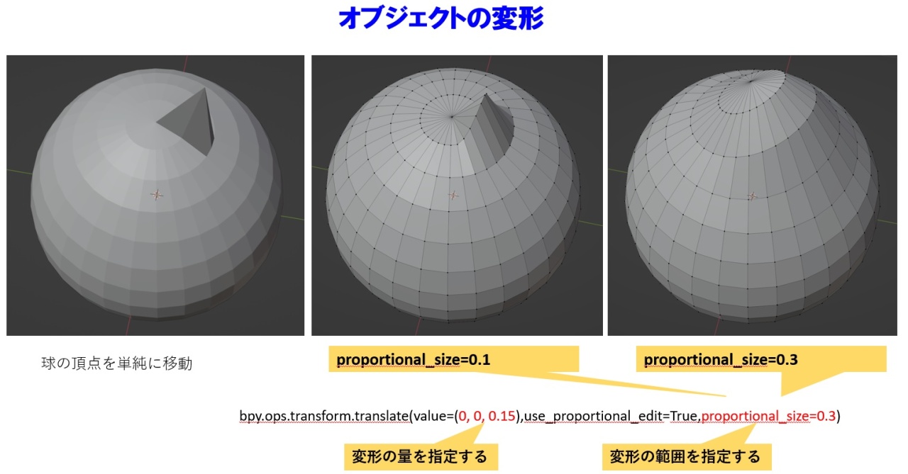
カボチャの形は、球の頂点を移動して変形させて作ります。
bdy.ops.transform.translate関数で変形の範囲をしていると指定した頂点の近傍の頂点も一緒に移動します。
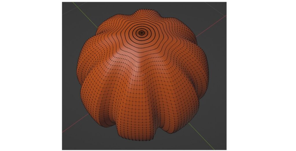
球の頂点を中心に向けて押し込むことで、カボチャの溝を作ります。
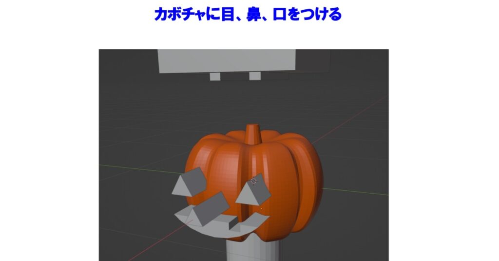
四角柱、三角柱、円柱でカボチャの目、鼻、口を作り、本体との差分をとることでくり抜きます。
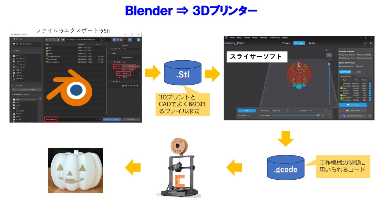
①Blenderのエクスポート機能を使って、3Dプリントでよく使われる.stlファイル形式で出力します。
②3Dプリンターに付属のスライサーソフトで工作機械の制御に使われる.gcodeに出力します。3Dプリンターのノズルが一番低い位置から0.1mmずつせり上がるように.gcodeを出力します。
③.gcodeを3Dプリンターに読み込ませて、カボチャを出力します。この例では約8時間かかりました。
カボチャの内側からLEDを光らせる
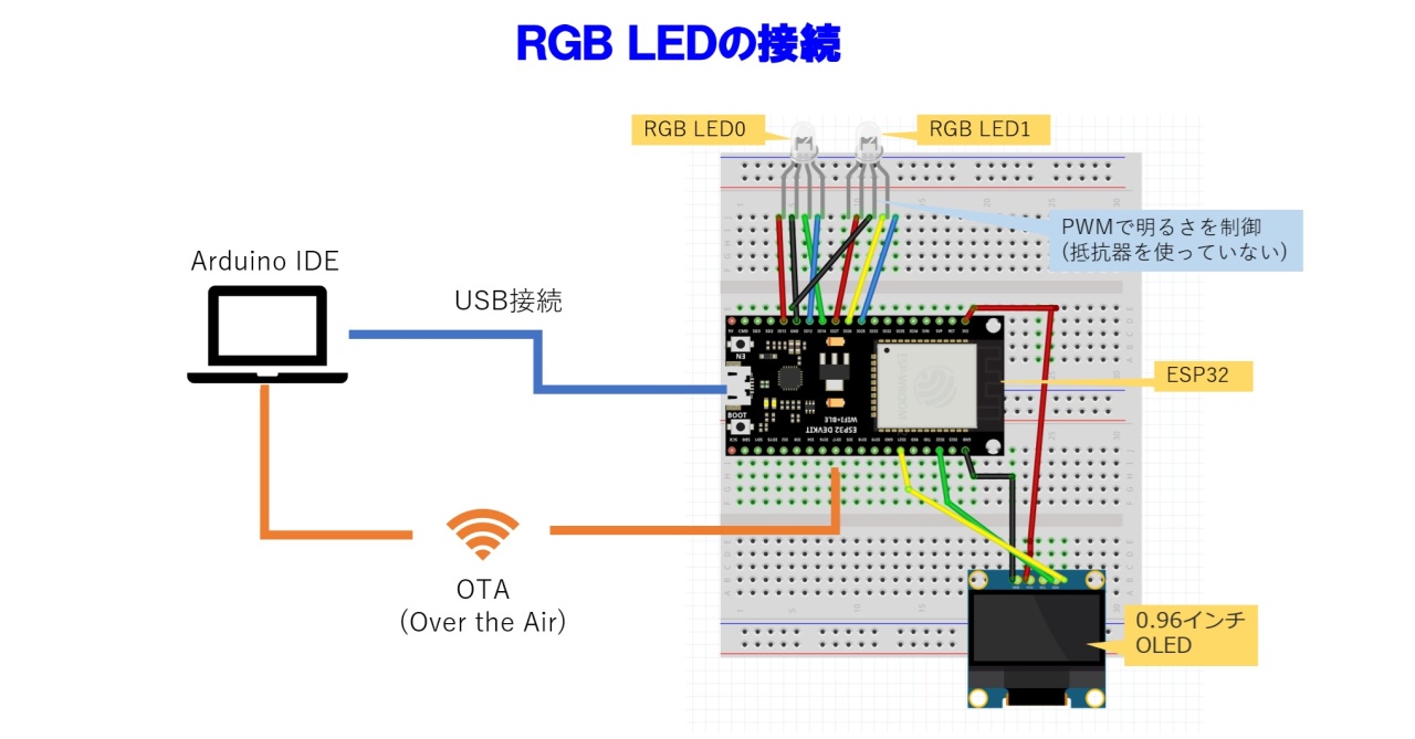
①カボチャの内部でカラーLEDを光らせます。カボチャ2個それぞれにカラーLEDを1個使います。カラーLEDはred, green, blueの3つのLEDを光らせて16,777,216通りの色を表現します。
②RGBの各色は256段階の強さを変えて光らせます。このコントロールをマイコンESP32で行います。どの程度の強さでコントロールしているのかの状態をOLEDに表示します。
③ESP32のプログラムは、PC上のArduino IDEで作ります。作ったプログラムはESP32とUSBケーブル接続またはWi-Fi接続でアップロードします。
マイコンのプログラムコード(halloween_singleLED)
/* halloween_singleLED        2024.9.26
【概要】
  1.2つの関数(th_bright_led, th_bright_led_270deg)をLED0, LED1用に2つずつ計4つのスレッドを起動する。
    機能は上図を参照。

  2.どのスレッドを動かすかは、2つのスレッドが停止したときに決める。
    スレッドの起動、停止はフラグで行う。
    フラグをを「起動」にするのはloop関数内で行い、「停止中」にするのはスレッド内で行う。
*/

//----- pwm設定用
const int frequ = 12800;    // [led_no_resi] 12800Hz
const int resolution = 8;   // [led_no_resi] 8bit Max 255
const int tick_interval = 200;      // tickのインターバル時間(ms)
uint8_t brightness_min = 0;         // pwm出力の最小値
uint8_t brightness_max = 128;       // pwm出力の最大値
int RGB_pins[][3] = {{13,12,14}, {27,25,26}}; // カラーLEDのpin番号(RGB) --- pwmは最大8チャネルまでなので2つのカラーLEDを制御できる。

//----- スレッド用
#include "freertos/task.h"
TaskHandle_t vth_bright_led[2];               // LEDタスクのハンドル
TaskHandle_t vth_bright_led_270deg_cycle[2];  // LEDタスクのハンドル

#include "SSD1306Wire.h"            // OLED SSD1306用ライブラリ
SSD1306Wire lcd(0x3c, SDA, SCL);    // SSD1306用インスタンス生成

//-------- OTA ここから
#include <WiFi.h>                         // OTA
#include <ArduinoOTA.h>                   // OTA
const char *ssid = "aterm-2b4139-a";      // OTA
const char *password = "3e00cfa4ba409";   // OTA
const IPAddress ip(192, 168, 0, 102);     // OTA ip固定 ----- アドレス
const IPAddress gateway(192, 168, 0, 1);  // OTA ip固定
const IPAddress subnet(255, 255, 255, 0); // OTA ip固定
const IPAddress dns1(192, 168, 0, 1);     // OTA ip固定
//-------- OTA ここまで

static unsigned long loop_cnt = 0; // ループカウント  [現在未使用]

/*----------------------------------------------------------------------------------
スレッド   カラーLEDの各色の明るさを270度周期で変える。
----------------------------------------------------------------------------------*/
// false:当該スレッドは停止中, true:当該スレッドは稼働中
bool th_270deg_running[] = {false, false}; // LED0, LED1

// 270度周期で各LEDの明るさを変える。 --- RGBの一つの色が100%のタイミングを作る。
void th_bright_led_270deg_cycle(void *pvParameters)
{
    int *value;
    value = (int *)pvParameters;
    int tIdx = *value; // 同じ関数が複数のタスクとして起動した時に識別するインデックス。

    while(1) {
      if (!th_270deg_running[tIdx]){
        delay(100);
        continue;
      }

      // 270度ループ
      for(int i=0; i<270; i++){

          if (tIdx==0){
            lcd.clear();   // OLEDの表示クリア
          }

          // 3本のpinループ
          for(int j=0; j<3; j++){
              int deg = i + j * 90;
              deg = deg % 270; // 1周期は270度
              if (deg > 180) {  // 180~270度は明るさを0にする。
                  deg = 0;
              }
              int bright = (int) abs((sin(radians(deg)) * 255));
              // 1つのLEDに明るさを設定する。
              bright = map(bright, 0, 255, brightness_min, brightness_max);  // 明るさ(0~255)をパルス幅(100~10000μs)に変換

              int led = RGB_pins[tIdx][j];
              ledcWrite(led, bright);

              // OLEDにLED_pinと明るさを表示する。
              lcd.drawString((j*3) * 15, (tIdx+1)*16, String(bright));
          }
          if (tIdx==0){
              lcd.display();
          }
          // 設定したカラーでLEDの表示をキープする。
          delay(tick_interval);
      }
    th_270deg_running[tIdx] = false;
    }
}

/*----------------------------------------------------------------------------------
スレッド   LEDの明るさを指定値から指定値まで指定された時間をかけて変える。
----------------------------------------------------------------------------------*/

// パターン2のカラーリスト [R,G,B,ディレイタイム]  ---- ろうそくの灯, 揺らぎのある炎のイメージ
int Color_tbl_candle[][4] = {
  {255,100,0,3},{255,100,0,80},
  {255,70,0,1},{255,70,0,2},  {200,70,0,1}, {150,50,0,1},  {255,80,0,2}, {200,100,0,2},
  {255,100,0,2},{255,100,0,40},
  {220,80,0,1}, {255,100,0,1},  {220,80,0,1}, {255,100,0,1}, {200,70,0,2}, {220,80,0,1},
  // 繰り返し
  {255,100,0,3},{255,100,0,70},
  {255,70,0,1},{255,70,0,2},  {200,70,0,1}, {150,50,0,1},  {100,150,0,1}, {200,100,0,2},
  {255,100,0,2},{255,100,0,40},
  {220,80,0,1}, {255,100,0,1},  {220,80,0,1}, {255,100,0,1}, {200,70,0,2}, {220,80,0,1}

};

// 単純にR->G->Bを3秒ごとに繰り返す。
int Color_tbl_rgb[][4] = {{200,0,0,20}, {200,0,0,50}, {0,170,0,10}, {0,170,0,50}, {0,0,255,10}, {0,0,255,50}};

// ネコ用カラーテーブル
int Color_tbl_cat[][4] = {{0,0,0,10},
  {140,0,255,20}, {140,0,255,80},     // darkmagenta
  {  0,  0,255,20}, {  0,0,255,80},   // blue
  {  0,200,  0,50},                   // lime
  {50, 40, 60,50},                     // darkolivegreen
  {255, 120,  0,50},                  // orange
  {200,  20,150,50}, {200,  20,150,80}, //  mediumvioletred
  {255,   0,  0,50}, {255,   0,  0,80}, //  red

  {180,0,100,20},

  {140,0,255,20}, {140,0,255,80},     // darkmagenta
  {  0,  0,255,20}, {  0,0,255,80},   // blue
  {  0,200,  0,50},                   // lime
  {50, 40, 60,50},                     // darkolivegreen
  {255, 120,  0,50},                  // orange
  {200,  20,150,50}, {200,  20,150,80}, //  mediumvioletred
  {255,   0,  0,50}, {255,   0,  0,50}, //  red

  {0,0,0,10}
};


// ネコ用カラーテーブル 静止画撮影用
int Color_tbl_cat_shot[][4] = {{0,0,0,10},


  {140,0,255,10}, {140,0,255,100},     // darkmagenta

  {  0,  0,255,10}, {  0,0,255,100},   // blue
  {  0,200,  0,10}, {  0,200,  0,100},                   // lime
  {0,0,0,10},
  {  0,220,  20,10}, {  0,220,  20,50},


  {0,0,0,10}
};


// カボチャ用カラーテーブル 静止画撮影用
int Color_tbl_candle2[][4] = {
{255,100,0,3},{255,100,0,100},
  {0,0,0,10},
{255,80,0,3},{255,80,0,100}
};


// led点灯コントロール・テーブル(LED0 / LED1)
int th_Color_tbl[2][40][4]; // コントロール・テーブルを対象とするLED側にコピーしてからスレッドを動作させる。

// led点灯コントロール・テーブルのサイズ(LED0 / LED1)
int th_color_tbl_size[2];

// false:当該スレッドは停止中, true:当該スレッドは稼働中(LED0 / LED1)
bool th_running[] = {false, false};

void th_bright_led(void *pvParameters)
{
    int *value;
    value = (int *)pvParameters;
    int tIdx = *value; // 同じ関数が複数のタスクとして起動した時に識別するインデックス。

    while(1) {
      if (!th_running[tIdx]){
        delay(100);
        continue;
      }

      // カラーテーブルの要素によるループ
      for(int i=0; i<th_color_tbl_size[tIdx]; i++){

          // 指定値から指定値までの移動かループ
          for(int k=0; k<th_Color_tbl[tIdx][i+1][3]; k++){
              if (tIdx==0){
                lcd.clear();   // OLEDの表示クリア
              }

              // 3本のpinループ
              for(int j=0; j<3; j++){
                int vs = th_Color_tbl[tIdx][i][j];   // 移動元の明るさ
                int ve = th_Color_tbl[tIdx][i+1][j]; // 移動先の明るさ
                int val = (int) (vs + (ve-vs)/th_Color_tbl[tIdx][i+1][3] * k); // 現在の回数の明るさ
                // 1つのLEDに明るさを設定する。
                int bright = map(val, 0, 255, brightness_min, brightness_max);  // 明るさ(0~255)をパルス幅(100~10000μs)に変換
                int led = RGB_pins[tIdx][j];
                ledcWrite(led, bright);

                // OLEDにLED_pinと明るさを表示する。
                lcd.drawString((j*3) * 15, (tIdx+1)*16, String(bright));
              }
              delay(tick_interval);
              if (tIdx==0){
                lcd.display();
              }
          }
      }
      th_running[tIdx] = false;
    }
}

// 指定されたテーブルをth_Color_tblを指定のインデックス要素にコピーする。
void tbl_copy(int Color_tbl[][4], int color_tbl_size, int idx){
  for(int i=0; i<color_tbl_size; i++){
    for(int j=0; j<4; j++){
      th_Color_tbl[idx][i][j] = Color_tbl[i][j];
    }
  }
}


void setup() {

  lcd.init();                       // ディスプレイを初期化
  lcd.setFont(ArialMT_Plain_16);    // フォントを設定
  lcd.flipScreenVertically();       // 表示反転(ボードにLCDを固定する向きに応じて)

  //-------- OTA ここから
  WiFi.config(ip,gateway,subnet,dns1);   // ip固定
  WiFi.mode(WIFI_STA);
  WiFi.begin(ssid, password);
  while (WiFi.waitForConnectResult() != WL_CONNECTED) {
    //Serial.println("Connection Failed! Rebooting...");
    delay(5000);
    ESP.restart();
  }
  ArduinoOTA.begin();
  Serial.println("IP address: ");
  Serial.println(WiFi.localIP());
  //-------- OTA ここまで

  // 2つのカラーLEDのpinにpwm出力を設定する。
  for(int i=0; i<2; i++){
    for(int j=0; j<3; j++){
      pinMode(RGB_pins[i][j], OUTPUT);
      ledcAttachChannel(RGB_pins[i][j], frequ, resolution, (i*3+j));
    }
  }

  // スレッド設定
  int idx0 = 0;
  int idx1 = 1;
  // タスクの起動
  xTaskCreateUniversal(th_bright_led, "th_bright_led0", 4096, &idx0, 1, &vth_bright_led[idx0], 0);
  xTaskCreateUniversal(th_bright_led, "th_bright_led1", 4096, &idx1, 1, &vth_bright_led[idx1], 1);
  xTaskCreateUniversal(th_bright_led_270deg_cycle, "th_bright_led_270deg_cycle0", 4096, &idx0, 1, &vth_bright_led_270deg_cycle[idx0], 0);
  xTaskCreateUniversal(th_bright_led_270deg_cycle, "th_bright_led_270deg_cycle1", 4096, &idx1, 1, &vth_bright_led_270deg_cycle[idx1], 1);

  // IPアドレスを表示する。
  lcd.clear();                      // 表示クリア
  char buf_s[32];
  sprintf(buf_s, "IP%s", WiFi.localIP().toString().c_str());
  lcd.drawString(0, 0, buf_s);     // LCDにIPアドレス表示
  lcd.display();                   // 指定された情報を描画
  delay(3000);
}

int seq_LED0 = -1;
int seq_LED1 = -1;

void loop() {
  ArduinoOTA.handle(); //-------- OTA

    //--------------- インデックス0のLED ---------------

    if (!th_running[0] && !th_270deg_running[0]) { // どのスレッドも動作していないときに次のシーケンスに移ることができる。
      seq_LED0++; // シーケンスを進める

      /*

          //--- 270度周期で各LEDの明るさを変える。
          th_270deg_running[0] = true;

          //--- カラーテーブル[Color_tbl_candle2]に従って点灯する。
          th_color_tbl_size[0] = sizeof(Color_tbl_candle2) / sizeof(Color_tbl_candle2[0]); // 3色単位の要素数
          tbl_copy(Color_tbl_candle2, th_color_tbl_size[0], 0); // スレッドで使うコントロール・テーブルにコピーする。
          th_running[0] = true; // スレッドを動作させる。

      */

      if (seq_LED0 == 0){
          //--- カラーテーブル[Color_tbl_candle]に従って点灯する。
          th_color_tbl_size[0] = sizeof(Color_tbl_candle) / sizeof(Color_tbl_candle[0]); // 3色単位の要素数
          tbl_copy(Color_tbl_candle, th_color_tbl_size[0], 0); // スレッドで使うコントロール・テーブルにコピーする。
          th_running[0] = true; // スレッドを動作させる。

      } else if (seq_LED0 == 1){
          //--- カラーテーブル[Color_tbl_candle]に従って点灯する。
          th_color_tbl_size[0] = sizeof(Color_tbl_candle) / sizeof(Color_tbl_candle[0]); // 3色単位の要素数
          tbl_copy(Color_tbl_candle, th_color_tbl_size[0], 0); // スレッドで使うコントロール・テーブルにコピーする。
          th_running[0] = true; // スレッドを動作させる。

      } else if (seq_LED0 == 2){
          //--- 270度周期で各LEDの明るさを変える。
          th_270deg_running[0] = true;

      } else {
        seq_LED0 = -1; // シーケンスを初期値に戻す。
      }

    }

    //--------------- インデックス1のLED ---------------
    if (!th_running[1] && !th_270deg_running[1]) {
      seq_LED1++; // シーケンスを進める

      /*
          //--- カラーテーブル[Color_tbl_rgb]に従って点灯する。
          th_color_tbl_size[1] = sizeof(Color_tbl_rgb) / sizeof(Color_tbl_rgb[0]); // 3色単位の要素数
          tbl_copy(Color_tbl_rgb, th_color_tbl_size[1], 1); // スレッドで使うコントロール・テーブルにコピーする。
          th_running[1] = true; // スレッドを動作させる。


         //--- カラーテーブル[Color_tbl_cat_shot]に従って点灯する。
          th_color_tbl_size[1] = sizeof(Color_tbl_cat_shot) / sizeof(Color_tbl_cat_shot[0]);
          tbl_copy(Color_tbl_cat_shot, th_color_tbl_size[1], 1);
          th_running[1] = true;

      */


      if (seq_LED1 == 0){
         //--- カラーテーブル[Color_tbl_cat]に従って点灯する。
          th_color_tbl_size[1] = sizeof(Color_tbl_cat) / sizeof(Color_tbl_cat[0]);
          tbl_copy(Color_tbl_cat, th_color_tbl_size[1], 1);
          th_running[1] = true;
      } else if (seq_LED1 == 1){
          //--- カラーテーブル[Color_tbl_candle]に従って点灯する。
          th_color_tbl_size[1] = sizeof(Color_tbl_candle) / sizeof(Color_tbl_candle[0]); // 3色単位の要素数
          tbl_copy(Color_tbl_candle, th_color_tbl_size[1], 1); // スレッドで使うコントロール・テーブルにコピーする。
          th_running[1] = true; // スレッドを動作させる。
      } else {
        seq_LED1 = -1;
      }


    }
    loop_cnt++;
    delay(tick_interval);
} 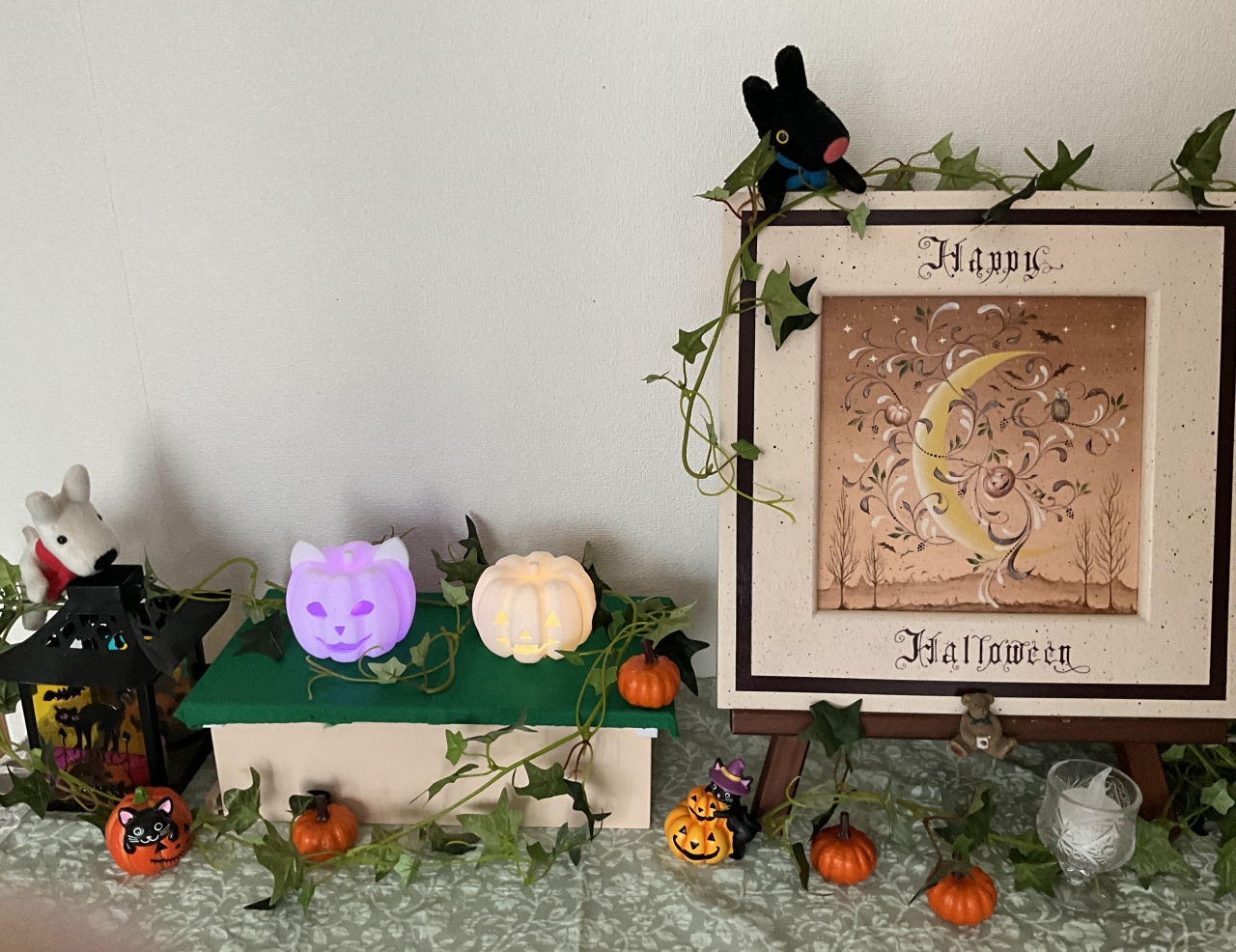
玄関に飾ってみました。カボチャの下の箱は、木製のテッシュボックスです。この中にマイコンを格納しています。
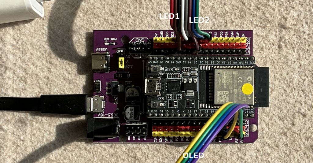
マイコンの配線
| LED番号 | Pin番号 | コード色 | LEDリード線 |
|---|---|---|---|
| 1 | 13 | 赤 | R |
| 1 | GND | 茶 | GND |
| 1 | 12 | 黒 | G |
| 1 | 14 | 白 | B |
| 2 | 27 | 灰 | R |
| 2 | GND | 紫 | GND |
| 2 | 26 | 青 | G |
| 2 | 25 | 緑 | B |